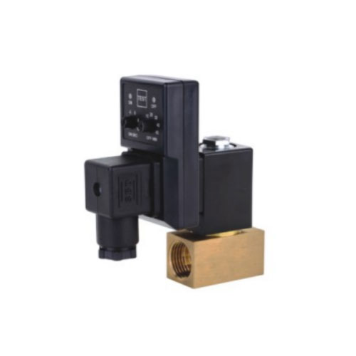
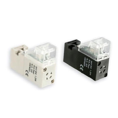
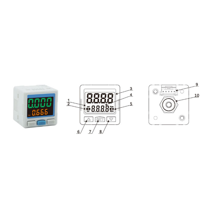
High Precision Digital Switch
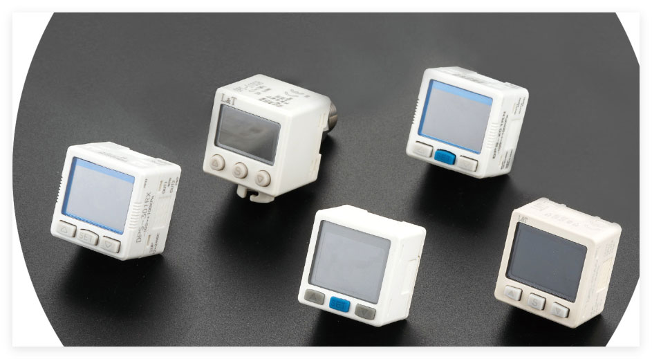
High Precision Digital Switch, one of the the pneumatic accessories, it used in in the field of pneumatic tools bring significant improvements and advantages. Our factory offer the item and Muffler Silencer, Filter, Shock Absorber etc, purpose to provide effective and professional service.
Send Inquiry
Pneumatic tools, usually rely on compressed air to drive working parts. After use High Precision Digital Switch, make pneumatic tools higher accuracy, flexibility, safety and energy efficiency, making them better role in many fields.
Product Feature:
1 High-precision control: achieve accurate switching action, error range is extremely small, to ensure the accuracy and stability of the system.
2. Digital operation: Use digital signals for control and feedback, good compatibility with digital systems, easy to integrate and intelligent control.
3. Fast response: It has a very short response time and can quickly switch the switch state to meet the application scenarios with high real-time requirements.
4. Programmability: the parameters and working mode of the switch can be set programmatically to adapt to different application requirements.
5. Strong anti-interference ability: It can effectively resist external interference and ensure the accuracy and reliability of the switch action.
High Precision Digital Switch Applications:
1. Industrial automation control system: On the production line, the precise start, stop, speed regulation and other operations of the equipment are accurately controlled.
2. Medical equipment: such as medical imaging equipment, surgical instruments, etc., to ensure the accurate operation and safe operation of the equipment.
3. Aerospace field: Used in various control systems of aircraft, satellites and other aircraft to ensure the high reliability and precision of the system.
4. Scientific research experimental equipment: Provide accurate switch control for all kinds of scientific research experiments to ensure the accuracy of experimental data.
5. New energy field: such as solar power generation, wind power generation control system, optimize energy collection and conversion efficiency.
6. Automotive electronics: including automatic driving system, engine control system, etc., to improve the performance and safety of the car.
7. Smart home appliances: such as high-end air conditioners, refrigerators, etc., to achieve accurate temperature, humidity and other parameters control.
Product Specification:
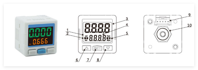
| No. | Name |
| 1 | Pressure unit |
| 2 | Group 1 switch output indicator |
| 3 | Main display area(pressure/setting) |
| 4 | Secondary display area (function Settings) |
| 5 | Group 2 switch output indicator |
| 6 | Up key |
| 7 | Set function key |
| 8 | Down key |
| 9 | Electrical interface |
| 10 | Pressure connection |
| Models | DPS-201(Mix) | DPS-202(negative pressure) | DPS-210(positive pressure) | ||
| Pressure testing | Measurement range | -100kPa~100kPa | -100kPa~0kPa | -0.100kPa~1.000kPa | |
| Setting range | -100kPa~100kPa | -100kPa~0kPa | -0.000kPa~1.000kPa | ||
| Withstand voltage | 500kPa | 500kPa | 1.500MPa | ||
| Pressure form | Non-combustible, non-corrosive gas, surface measurement | ||||
| Measurement accuracy | ≤±2%F.S. | ||||
| Temperature error | ≤±3%F.S. | ||||
| Measurement mode | Delayed mode | ||||
| Comparison mode | |||||
| Pressure connection | R1/8, NPT1/8, G1/8. M5 | ||||
| Pressure indicators | Basic description | Double row LCD screen | |||
| Status display | Output status display | ||||
| Display mode | LCD/LED-ADJ | ||||
| Input power | Voltage range | DC 24V 10% | |||
| Consumed power | 40Ma Max | ||||
| output signal | Transistor output |
NPN PNP Output Current: 80mA MAX Output Current: 80mA MAX Voltage Drop: ≤1V Voltage Drop: ≤1V |
|||
| Analog output |
Analog voltage output Analog current output Signal amplitude:1-5V Signal amplitude:4-20mA Load resistance: ≥1KΩ Load resistance: ≤400Ω |
||||
| Response time | Adjustable: 2.5ms, 20ms, 100ms, 500ms, 1000 ms, 2000 ms, | ||||
| Short-circuit protection | Yes | ||||
| Environmental proof | IP level | IP40 | |||
| Environment temperature | Environment temperature:0-50℃ | ||||
| Ambient humidity | Ambient humidity:35~80% RH | ||||
| Isolation voltage | 1000VAC /MIN | ||||
| Insulation resistance | ≥50MΩ(500VDC) | ||||
| Impact resistance | MAX 100m/S² | ||||
| Vibration resistance | Amplitude1.5mm, 10HZ~500HZ, | ||||
Ordering code:
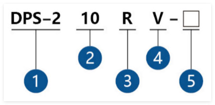
1. Serial code
2.Measurement range:
0.1:-100~100kPa
0.2:-100~0kPa
10:-100~1000kPa
3.Pressure connection
R: R1/8 Connector(M5)
N:NPT1/8 Connector(M5)
G: G1/8 Connector(M5)
C4: 4# quick-insert
C6:6#quick quick-insert
L4: 4#quick quick-insert
L6:6#quick quick-insert
4. Output form
N:2ways NPN output
P:2ways PNP output
A:1 way NPN+1way 4~20mA
V: 1way NPN+1way 1~5V
B:1 way PNP +1 way 4~20mA
W:1way PNP+1way1~5V
NV:2ways NPN +1way 1~5V
PV: 2ways PNP+1ways1~5V
5.Options
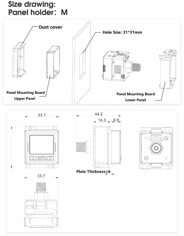
M:Panel
N:Panel+dust cover
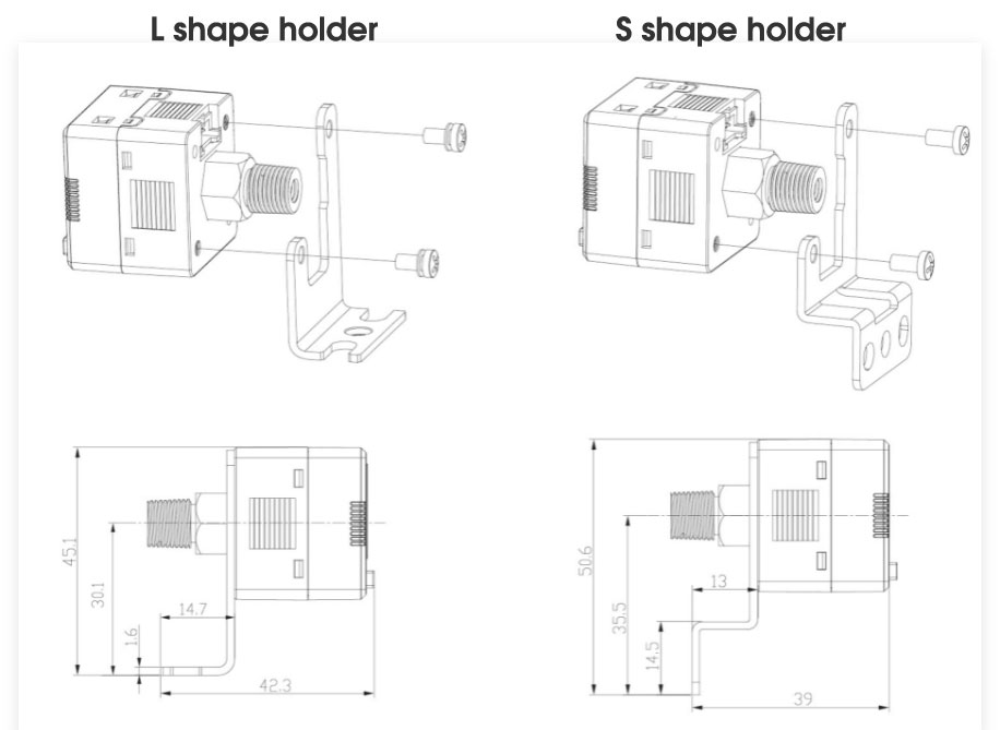
Z: L shape holder
S: S shape holder
Shortcut function
Clear data
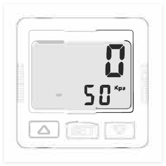
Measurement mode: Simultaneously press  Until"0.000".Release.
Key lock and unlock
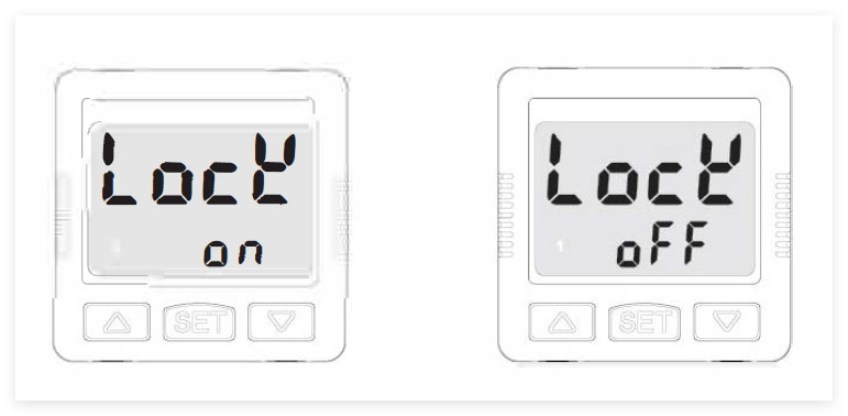
Key lock: Measurement mode: Simultaneously press  ,until LOCK ON, then release.
Press to unlock: Measurement mode: Simultaneously press  , until LOCK OFF, then release.
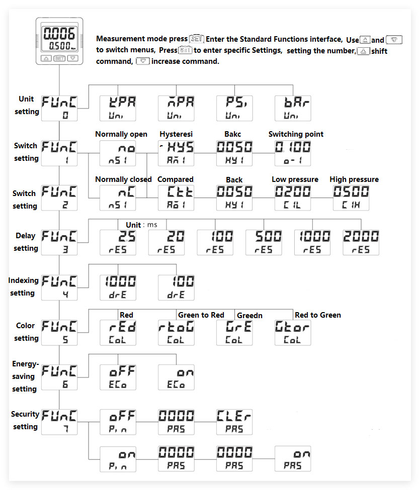
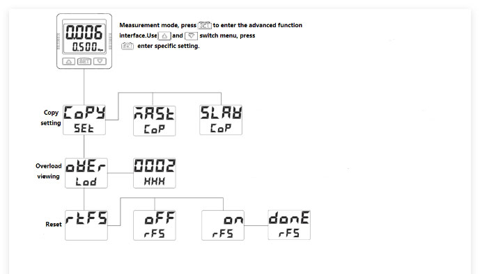
Easy setup function
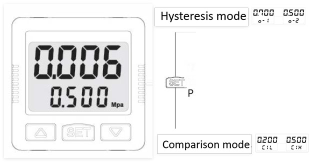
Measurement mode press  , then press
  or
or  adjust data, confirm and next menu. Set in sequence, until back me back measurement mode.
Connection solution:
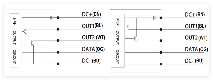
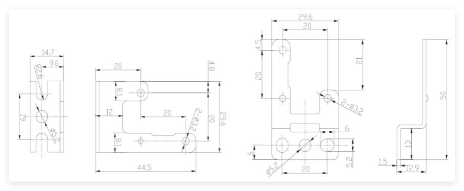
External dimensions & pressure interfaces
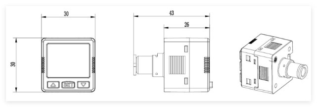
C6 Interface dimensions drawing
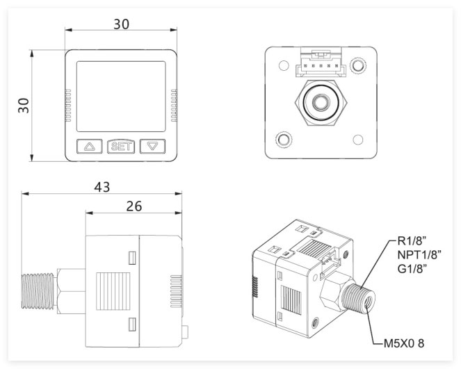
Assemble holder
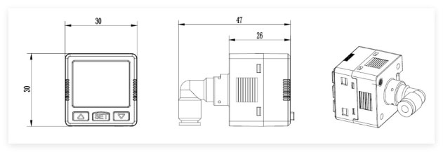
L4 Interface dimensions drawing

L6 Interface dimensions drawing

Conductor size:
Error code specification
| Erro Prompt | Reason of prolblem | Solution |

|
Out of 0 range | Zero range limit 10%F.S. Do not overset |

|
The switch output over range | Please check whether the output connection line is in short circuit load and other problems |

|
The pressure setting logic incorrect | Delay mode: HYS value <0-1; Comparison mode: HYS value <C1L<C1H |

|
Stored data exception | Chip abnormal maintenance |

|
The password incorrect | Please enter the correct password |

|
Copy communication exception | Data verification error, please copy again |

|
Pressure out of range | Please lower the air source pressure to the range |

